
Drone embedded systems are sophisticated computing software with a distributed architecture and real-time operation. Designed to safely control physical objects in three-dimensional space with six degrees of freedom, they must instantly respond to ongoing environmental changes, but are severely limited by available hardware resources. Actually, this is why we decided to highlight the most relevant embedded system design challenges in this article.
Core Challenges in Embedded System Design for Drones
As a leading Ukrainian developer of UAV software solutions, after years of experience, we can highlight the following challenges in embedded system design.
Real-Time Processing Constraints
In UAV software, computational latency is equivalent to a system failure. If the module responsible for stabilization fails to update the motor control algorithm in time, the drone will lose stability. Here are the main challenges associated with this:
- Latency issues. Due to the end-to-end ping from the change in the drone's position in the air to the change in the PWM signal on the speed controllers, latency can include the time it takes to poll sensors via the SPI/I2C buses, plus the time required to trigger filtering algorithms, and the time needed to calculate the PID stabilization loop. It’s important to ensure that this total doesn’t exceed 1-2 milliseconds.
- Timing precision. If the integration step in the UAV dynamics equations begins to fluctuate by even a few microseconds, this will quickly lead to accumulated positioning errors and frame vibrations.
- RTOS importance. Here, it makes sense to abandon standard general-purpose OSes in favor of a hard RTOS like FreeRTOS or NuttX, which allows for preemptive multitasking based on predefined priorities. We also sometimes use DMA mechanisms – this helps us free up processor resources when interacting with SPI/UART.
Power Consumption and Battery Limitations
Every milliampere-hour consumed by a UAV's processor reduces its flight time. This is why it's crucial to achieve trade-offs in the following areas:
- Performance vs. power consumption. Since using chipsets like the STM32H7 at 480 MHz or SoCs with ARM Cortex-A/Cortex-M cores requires hundreds of milliamps, it's crucial to implement dynamic frequency and voltage adjustments and put unused microcontroller peripherals into deep sleep modes, returning the kernel to maximum performance only when performing complex spatial maneuvers or obstacle avoidance.
- Weight vs. performance. Increasing battery capacity increases the UAV’s weight, requiring the installation of more power-hungry propeller assemblies. That’s why we design the firmware to utilize 100% of the energy-efficient ARM Cortex-M4/M7 chips, thereby minimizing the need for heavy coprocessors for onboard vision.
Hardware Constraints and Miniaturization
Choosing the right electronics for a drone frame involves both squeezing spare millimeters and addressing overheating.
- Limited space. The dense placement of printed circuit boards in small-form-factor UAVs places strict constraints on the routing of high-speed interfaces. To avoid interference from ESC power lines, we design boards with 6-10 layers, continuous ground planes, and shielding for analog circuits.
- Heat dissipation. Without forced cooling, powerful UAV processors quickly experience thermal throttling. To avoid this, it's best to use thermally conductive dielectric spacers and install thermal vias under highly heated components.
- Component selection. Industrial-grade UAVs must withstand operation in the -40°C to +85°C range and be vibration-resistant, making it advisable to replace conventional quartz crystals with specialized MEMS oscillators.
Sensor Integration and Data Fusion
Data from any single sensor contains noise and drift, which is why it's so essential to combine disparate physical quantities at the software level:
- Dissimilar data streams. The system must be able to collect data from a high-frequency inertial unit operating at frequencies of 1-8 kHz, a low-frequency GPS/GNSS receiver operating in the 5-10 Hz range, as well as a magnetometer, a barometric altitude sensor, and lidars.
- Time synchronization issues. Signals from different sensors arrive at the processor with different propagation delays. Therefore, if, for example, accelerometer readings taken 1 ms ago are combined with current gyroscope readings, the orientation algorithm will produce an incorrect tilt vector. This can be addressed by timestamping each measurement at the timer interrupt level and buffering the data for subsequent time alignment.
- Noise filtering. Direct integration of noisy data from the accelerometer leads to a coordinate shift, and this is where data integration algorithms like the extended Kalman filter come in handy, as they filter out high-frequency vibration noise, thereby eliminating gyroscope drift.
Communication and Signal Reliability
One of the main design issues in embedded system development is to ensure that even with partial packet loss, the flight controller will correctly execute the mission (that is, the operator or ground control station shouldn’t lose telemetry under any circumstances).
- Wireless instability. In real-world conditions, UAVs often experience multipath fading, so it's important to use timeout handling protocols. Specifically, if control packets stop arriving within a specified window of, say, 500 ms, the firmware immediately switches the system to pre-failsafe mode, reducing the speed and stabilizing the device until either the link is restored or a decision to return is made.
- Interference. In industrial areas, electromagnetic noise levels are off the charts, so to prevent this, we typically use protocols with pseudo-random frequency hopping. This requires synchronizing hardware timers with the transceiver at the microcontroller level so that both the transmitter and receiver switch channels synchronously.
- Bandwidth limits. Since transmitting raw data over a radio channel is impossible, developers should use lightweight serialization protocols such as MAVLink, with its up to 12-byte overhead for service headers.
Firmware Reliability
The codebase complexity lies in the fact that developers essentially have no right to allow faults in segmentation or thread hangs.
- Difficulties in code debugging. Debugging UAV firmware with a conventional JTAG programmer is simply impossible because you cannot stop the processor with a breakpoint when the UAV moves at 60 km/h. This necessitates aggressive logging on high-speed onboard flash memory via the QSPI bus, real-time instruction tracing, and stress testing of algorithms in simulators.
- OTA updates. Any power failure during an OTA update can brick the board. Therefore, it's crucial to design memory mapping with three zones: the immutable bootloader, the current firmware, and the boot image. This enables the checksum of the new image to be verified first, and only after its validation, the interrupt vector pointer is adjusted accordingly.
- Stability issues. To prevent complete system lockups, it's important to set up an independent watchdog clocked by a separate built-in RC oscillator. If the main program loop freezes and doesn't reset the timer within 100-150 milliseconds, a hardware reset of the processor will be triggered, allowing the drone to regain control during a fall.
Fault Tolerance and Drone Safety
An embedded system must be designed with the understanding that if something can fail, it will definitely happen in flight. This is why it's so crucial to include:
- Fail-safe mechanisms. If the extended Kalman filter detects a compass discrepancy, the system must be able to instantly switch from GPS-dependent navigation mode to altitude hold mode using the barometer and accelerometers. Moreover, if the battery voltage drops significantly, the system will initiate an automatic forced landing algorithm or, alternatively, an automatic return to the takeoff point.
- Redundant systems. In industrial flight controllers, it's worth duplicating critical sensors. For example, we often install 2-3 separate IMUs from different manufacturers on vibration-decoupled damping platforms, powering them from different lines of LDO voltage regulators and implementing a majority voting algorithm for all of them.
- Crash prevention. The developers must build kinematic limits into the control loop – thanks to this, even if the operator suddenly moves the control stick all the way, the firmware will smooth out the command using the S-curve trajectory generator algorithm.
Vulnerabilities in the Code
A firmware vulnerability can lead to complete loss of control of the drone or, worse, physical damage:
- Hacking risks. This type of software is often vulnerable to man-in-the-middle attacks, command injections, and GPS spoofing. These security risks must be mitigated at the software level by implementing the extended Kalman filter, which continuously compares the GPS coordinate increment with the integral of the acceleration vector from the accelerometers. If a significant discrepancy arises between them, the system immediately switches the drone to autonomous return-to-home mode.
- Data encryption. Conventional implementations of cryptographic algorithms are too resource-intensive for real-time microcontrollers, so it's better to use microcontrollers with hardware cryptoprocessors, such as those in the STM32H7/F7 family, which enable symmetric AES-GCM-256 encryption at the DMA level.
- Secure communication. It's better to abandon the basic MAVLink 1.0/2.0 without signatures in favor of secure specifications and mutual authentication, when a cryptographic handshake occurs via the ECDH protocol, when the remote control and the drone are turned on, and the drone itself uses a unique private key localized in a secure area of the microcontroller's memory.
Scalability and System Integration
In automation scenarios, embedded systems must seamlessly integrate into global information networks, and it's crucial to overcome some challenges in the following aspects:
- Integration with cloud platforms and IoT. Implementing a heavy protocol stack for communicating with general platforms and IoT systems directly on a flight microcontroller is impossible due to the high risk of unpredictable latencies and rapid stack overflow. Therefore, it makes much more sense to divide the architecture into two layers: the Flight Controller for real-time tasks and the Companion Computer for higher-level tasks.
- Expanding functionality. To ensure that adding, for example, a laser rangefinder or a multispectral camera doesn't require redesigning the entire hardware platform, you can use a bus topology based on the industrial CAN interface and the UAVCAN protocol. This bus operates at speeds of up to 1 Mbps (or up to 5 Mbps for CAN-FD), and allows each new device to be equipped with its own low-cost microcontroller and connected to the shared bus in parallel.
To sum up, let’s check the table highlighting the aforementioned design challenges in embedded systems.
| Challenge area | Main issue | Why it matters in drones |
|---|---|---|
| Real-time Processing | Microsecond jitter and latency | Asynchronous sensor polling leads to a phase shift in the PID controller and subsequent drone crashes. |
| Power and battery | Fast discharge and intense heat generation | Every extra gram of battery weight reduces the useful flight load. |
| Hardware and thermal | High vibration loads and rapid overheating | Frame vibration creates noise in the IMU, while processor overheating causes frequency throttling. |
| Sensor integration | Desynchronization and zero drift | Sensors operate at different frequencies, causing false velocity accumulation. |
| Communication | Signal fading and interference | Loss of control link at critical altitudes or in urban areas. |
| Firmware reliability | Streams freezing during OTA | An update error crashes the device while it's in flight. |
| Safety and redundancy | Single points of failure | Failure of a single sensor or motor leads to a crash. |
| Security vulnerabilities | Spoofing and interception of control of a UAV | Drone forced landing by an attacker or log theft. |
| Scalability and IoT | Lack of computing resource | The inability to run AI algorithms and a heavy network stack on a single MCU. |
Best Practices to Overcome Embedded System Design Challenges
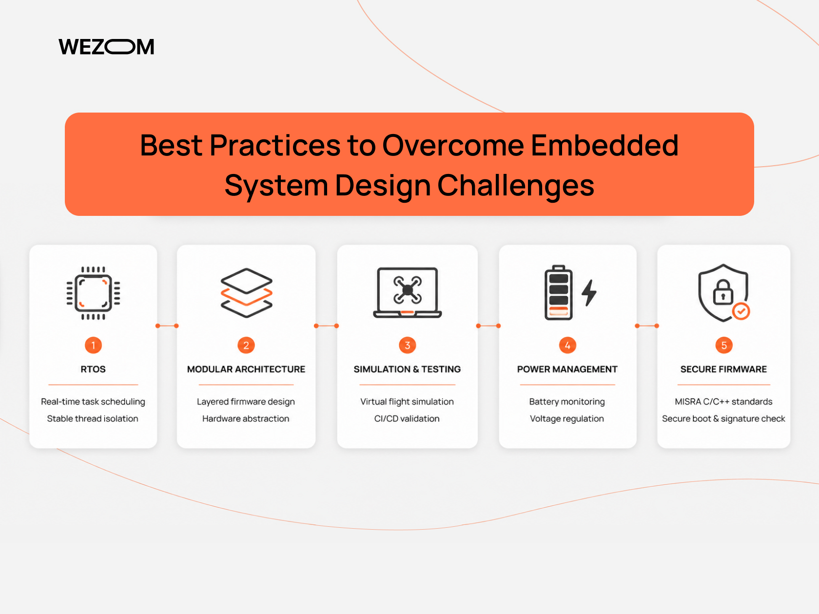
Over the years of designing industrial unmanned aerial systems, we have developed a set of internal best practices to overcome the most typical challenges of embedded systems.
Use of RTOS
For UAV control systems, bare-metal programming based on a while(1) super-loop is only suitable for the simplest use cases, while in more complex projects, we still use RTOSes. NuttX or Zephyr ones are particularly helpful here, with an RTOS scheduler that guarantees that if the Rate Control Loop calculation task has the highest priority and must be executed every 1000 µs (at 1 kHz), the startup jitter won’t exceed a few nanoseconds (and any other low-priority task will be immediately preempted).
We also strictly delimit memory between threads – that is, if the camera gimbal data exchange thread encounters a null-pointer-dereference error during operation, the RTOS will isolate this thread and restart it, preventing the flight stabilization algorithms from stalling.
Modular Architecture
Monolithic code doesn’t demonstrate efficiency in the long term, so we build the firmware using a layered modular model, separating the physical layer, business logic, and control algorithms.
In particular, in WEZOM, the code for the stabilization/navigation algorithms is most often written in C/C++ without direct binding to the registers of a specific processor (instead, all sensor requests are made through abstraction interfaces). This allows us to migrate from one chip to another in a matter of days, without affecting the complex logic of the flight controller.
We also frequently use the lightweight Micro Object Request Broker pattern within the firmware, which allows us to eliminate cyclic dependencies in the code, as the modules won’t directly know anything about each other because of their autonomy.
Simulation and Testing
Real-world flight tests often result in costly UAV failures, so every line of code must undergo multi-stage validation before being deployed.
To do this, we compile the flight controller code for a standard x86-64 architecture to run the executable on a CI/CD server and connect it to the flight simulator. This simulator then generates virtual sensor signals and sends them to the virtual flight controller, receiving motor commands in return.
In the next step, we take a real flight controller board, connect it to the simulator via debug interfaces, and generate real physical signals on the flight controller's SPI/I2C/ADC pins using the simulator board, thereby performing a flight simulation.
Efficient Power Management
We separate high- and low-current power domains to prevent MCU failures. Specifically, since the drone's power supply operates at voltages up to 50V, while the flight controller operates at 3.3V and 5V, we use buck regulators to initially lower the voltage, while the sensitive analog sensor units are powered by ultra-low-noise linear regulators with a high power supply rejection ratio.
We also use firmware that analyzes the internal resistance of each battery cell, the battery pack temperature, and the precise power consumption in coulombs, enabling dynamic recalculation of the remaining flight time.
Secure Firmware Design
Here, the focus is on buffer overflow protection. To achieve this, we adhere to MISRA C/C++ secure coding standards in critical flight modules, avoiding dynamic memory allocation during flight. This eliminates heap fragmentation and memory leaks, which can cause the controller to freeze after several hours of operation.
We also implement an internal bootloader, which is run at system startup (it must be written to a write-protected area of memory). It reads the developer's public key by calculating the SHA-256 hash of the main firmware image and verifying its digital signature using the ECDSA-256 algorithm. If the signature doesn't match, the board locks the motors and enters error indication mode.
Common Mistakes in Embedded Systems Design
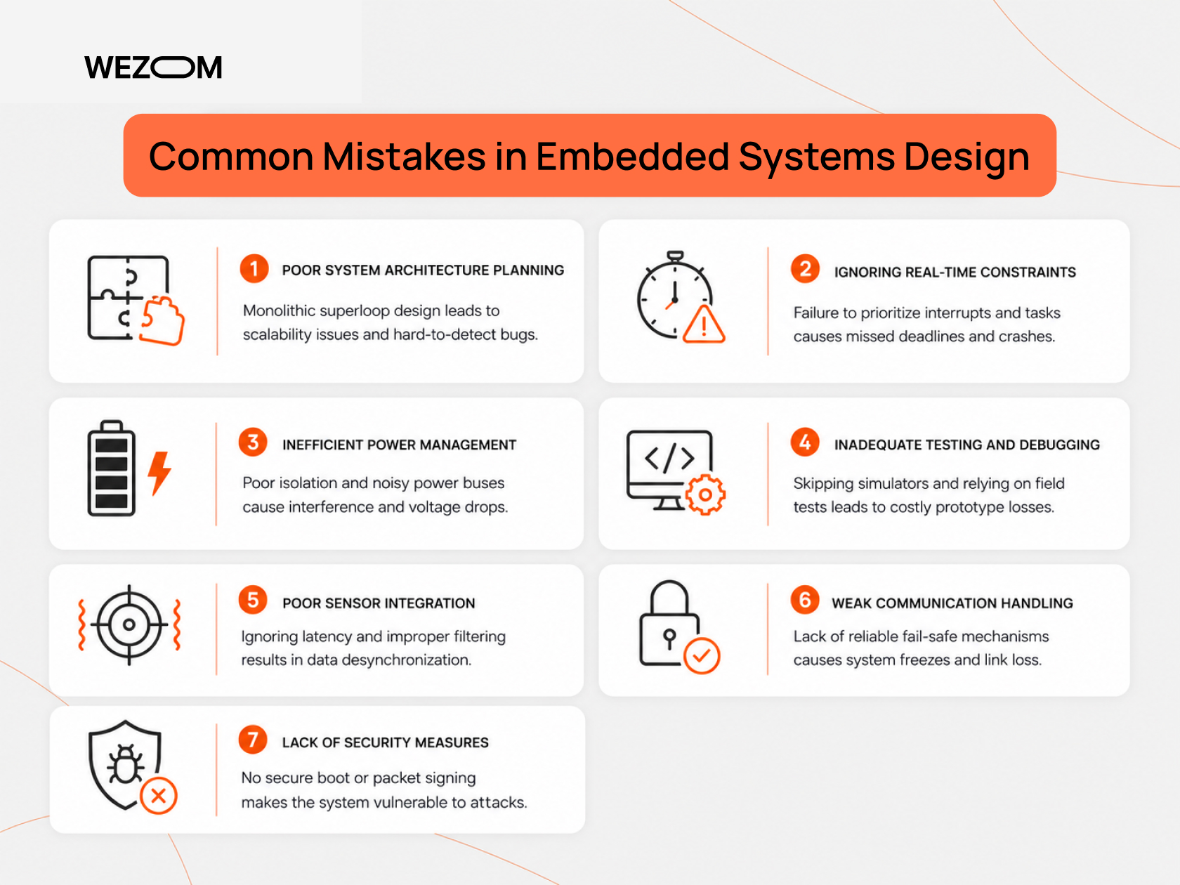
Over the years of auditing and refactoring other teams' projects, we've identified a number of common mistakes:
- Poor system architecture planning. Trying to fit all logic into a single monolithic superloop without using an RTOS leads to code scalability ceilings and the emergence of difficult-to-detect bugs.
- Ignoring real-time constraints. Failure to prioritize interrupts and tasks means the PID loop doesn't have time to update, and the drone simply crashes.
- Inefficient power management. Neglecting to isolate analog sensors from the ESC power buses causes strong electromagnetic interference on the gyroscopes and false triggering of the voltage drop protection.
- Inadequate testing and debugging. Neglecting the use of SITL/HITL simulators (in favor of field firmware testing) leads to costly prototype losses at the first software failure.
- Poor sensor integration. Ignoring latency between sensors and failing to filter high-frequency vibrations at the software level leads to data desynchronization.
- Weak communication handling. The lack of reliable fail-safe mechanisms leads to system freezes with the slightest loss of telemetry packets.
- Lack of security measures. Transmitting commands in cleartext without signing packets and the lack of secure boot make the drone an easy target for cyber attacks.
Conclusion
Considering all the challenges faced in designing an embedded system, to create a reliable industrial solution, it's essential to build in principles of hardware security and modularity from the ground up. Otherwise, you'll waste a ton of money and time on something that simply won't work properly in the field and will require constant optimization.
FAQ
What are the main challenges in embedded system design?
This is primarily to ensure hard real time with minimal control loop latency (i.e., within 1-2 ms) with restrictions on weight, dimensions, and power consumption of the device itself.
Why are drone embedded systems more complex than traditional ones?
Since the drone operates in a three-dimensional dynamic environment with six degrees of freedom, any jitter or flow freeze for hundredths of a second will lead to its destruction and a threat to the safety of those around it.
Why is sensor integration difficult in drones?
Each sensor operates at its own frequency, with its own delay and noise, so synchronizing them in time and filtering out noise without introducing loop delay is considered an extremely challenging task.
What are the challenges of scaling embedded systems?
This is a shortage of computing resources and microcontroller input/output ports when adding new functions (which is hardly possible without a modular bus architecture and separation of logic into a flight controller and companion computer).
How can companies overcome embedded system design challenges?
To achieve this, they must use professional RTOS systems, develop according to MISRA standards, implement hardware encryption/triple redundancy of sensors, and cover the code with automated tests in simulators before the first flight.
